


Directional local heating of workplaces and production areas
An important area of application of heaters of the EIUS-200 series is local heating of workplaces and production areas in unheated rooms such as workshops, garages, service stations, small workshops and warehouses, where constant or periodic economic heating is required, which does not require significant investment.
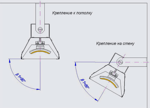
The efficiency of these heaters for local heating in large rooms and workshops, which is not cost-effective to heat entirely, has been confirmed. The design of the heaters allows them to be installed on a wall or ceiling with the possibility of directing the radiant flux at any angle to the horizon β1= 0-90 ° (see Fig. 1) In this case, the distance to the heated object depends on the type of heater and its electrical power. Comparative tests of different types of heaters have shown the advantages of ceramic emitters over panel, quartz tubular, carbon and halogen emitters (see "The use of heaters of various types in infrared heating systems"). The safety of directional radiation heating of a person with heaters EIUS is confirmed by the fact of their certification for use in medicine in the process of heating newborn children.
Calculations made according to a simplified method are applicable, as a rule, for extreme climatic conditions: open and semi-open unheated industrial premises with a low air temperature (+5 - + 16 ° C), warehouse and hangar rooms, open areas, etc. (see examples 1-5).
When using infrared heating in closed rooms (at temperatures from 0 to + 25 ° C), the power limits and the width of the comfort heating zone are determined according to the method detailed in the section "Infrared heating of the human body - standards and microclimate provision for industrial premises". (See also examples 6 and 7).
Simplified selection of the number of heaters and their electrical power
Heaters location diagrams and minimum permissible distances to workers in closed rooms with an ambient temperature of +5 - +16 ° С.
|
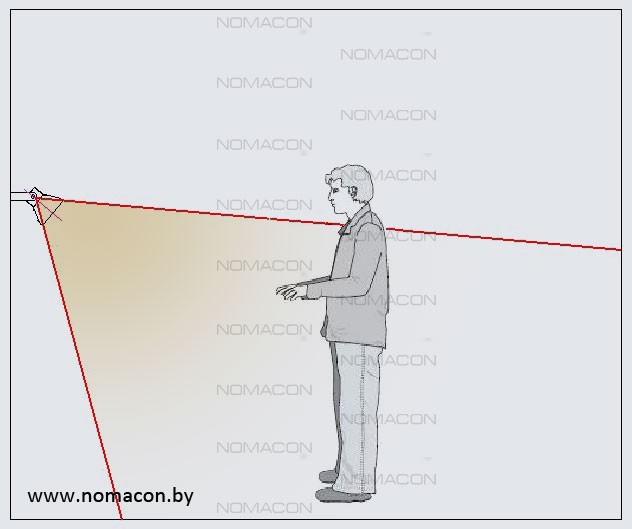
1. Directional frontal one-sided heating when the worker's head hits the heating area. |
||||
|
Heating circuit |
Permissible values of the intensity of thermal heating, W / m2 |
The minimum distance from the heater to the radiation surface (Ln1), m |
||
|
EIUS-211 |
EIUS-212 |
EIUS-213 |
||
|
|
Heating no more than 25-50% of the body surface, the intensity of heating the head no more than 60 W / m2 |
1,4 |
1,8 |
2,2 |
|
2. Directional frontal one-sided heating when the heating area hits the worker's torso. |
||||
|
|
Heating no more than 25-50% of the body surface, heating intensity of the trunk no more than 100 W / m2 |
1,0 |
1,4 |
1,7 |
|
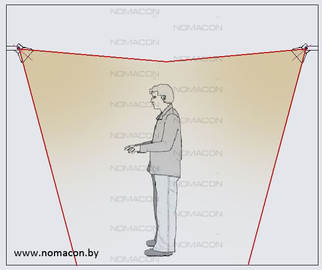
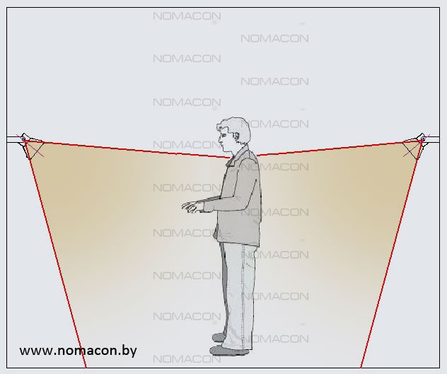
3. Directional frontal double-sided heating when the worker's head hits the heating area. |
||||
|
|
Heating more than 50% of the body surface, the intensity of heating the head is not more than 35 W / m2 |
1,8 |
2,4 |
2,9 |
|
4. Directional frontal double-sided heating when the heating area hits the worker's torso. |
||||
|
|
Heating more than 50% of the body surface, the intensity of heating the trunk is not more than 50 W / m2 |
1,5 |
2,0 |
2,4 |
|
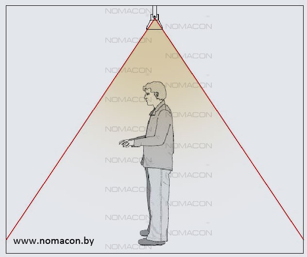
5. Heating the room with heaters installed on the ceiling. |
||||
|
|
Heating no more than 25-50% of the body surface, the intensity of heating the head no more than 60 W / m2 |
1,5 |
2,0 |
2,4 |
- Based on the above heating schemes select the heating mode for the worker: we determine the number of heaters - one or two and their position relative to the employee.
- Determine the real distance from the heater to the center of the workplace.
- According to the table determine the brand of the heater (EIUS-211, EIUS-212, EIUS-213);
Methodology for detailed calculation of the selection of the number of heaters and their electrical power
Example 1
It is required to select the EIUS heater and determine the optimal height of its installation on the wall for one-sided frontal directional heating from a height of more than 1.8 m with the worker's head falling into the area of the directed radial flux (see mode 1). In this case, the angle of inclination of the reflector to the horizontal is β1 = 30 °, the distance from the worker in the center of the workplace to the wall with the heater is A1 = 2.0 m, the average height of the employee is taken equal B1 = 1.75 m.
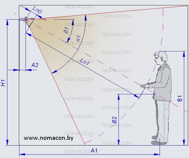
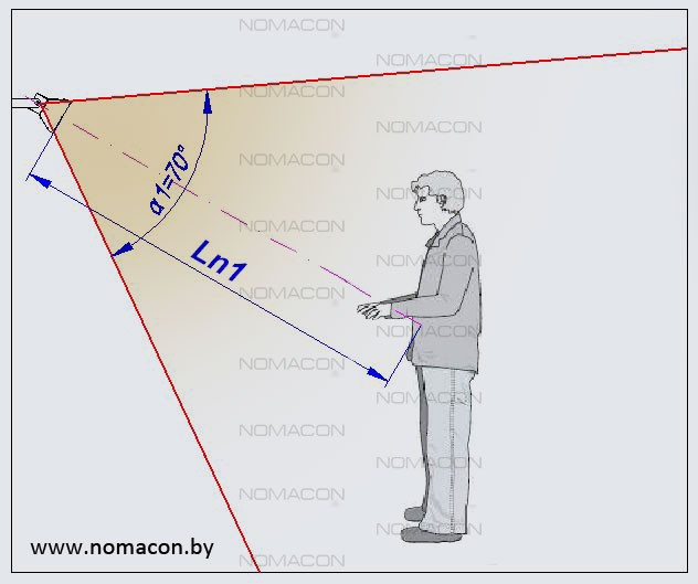
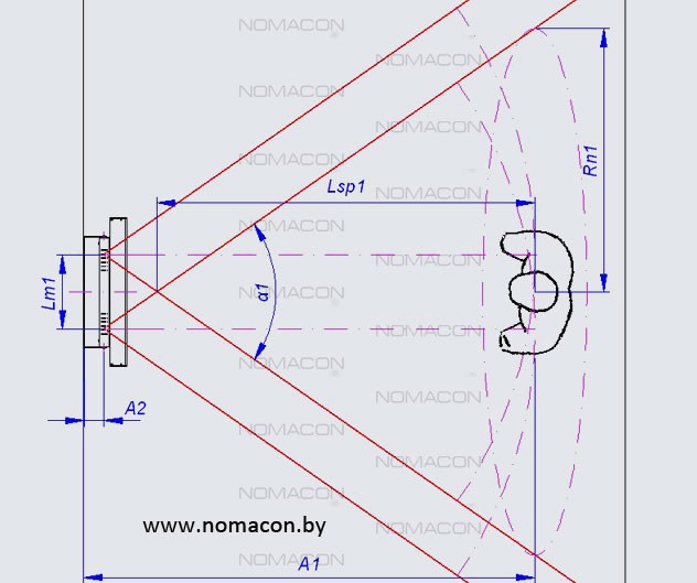
1) We draw up a heating scheme according to mode 1, taking into account the design parameters of the EIUS-200 heaters: A2 = 75 mm, Ln0 = 80.5 mm, α1 = 70 ° (see figure 2). With the optimal heating option, the central axis of the radiant flux (central normal to the radiation surface) should pass approximately through the middle of the body in height and at the same time B2 = (0,5 — 0,6) ⋅ B1... For calculations we accept B2 = 0.55 ⋅ B1, B2 = 0.9625 m.
2) The height of the heater installation is determined by the formula:H1 = 2.07 m.
3) The formula for determining the distance from the heater (radiation surface) to the worker's head will take the form:

Ln1 = 1.87 m.
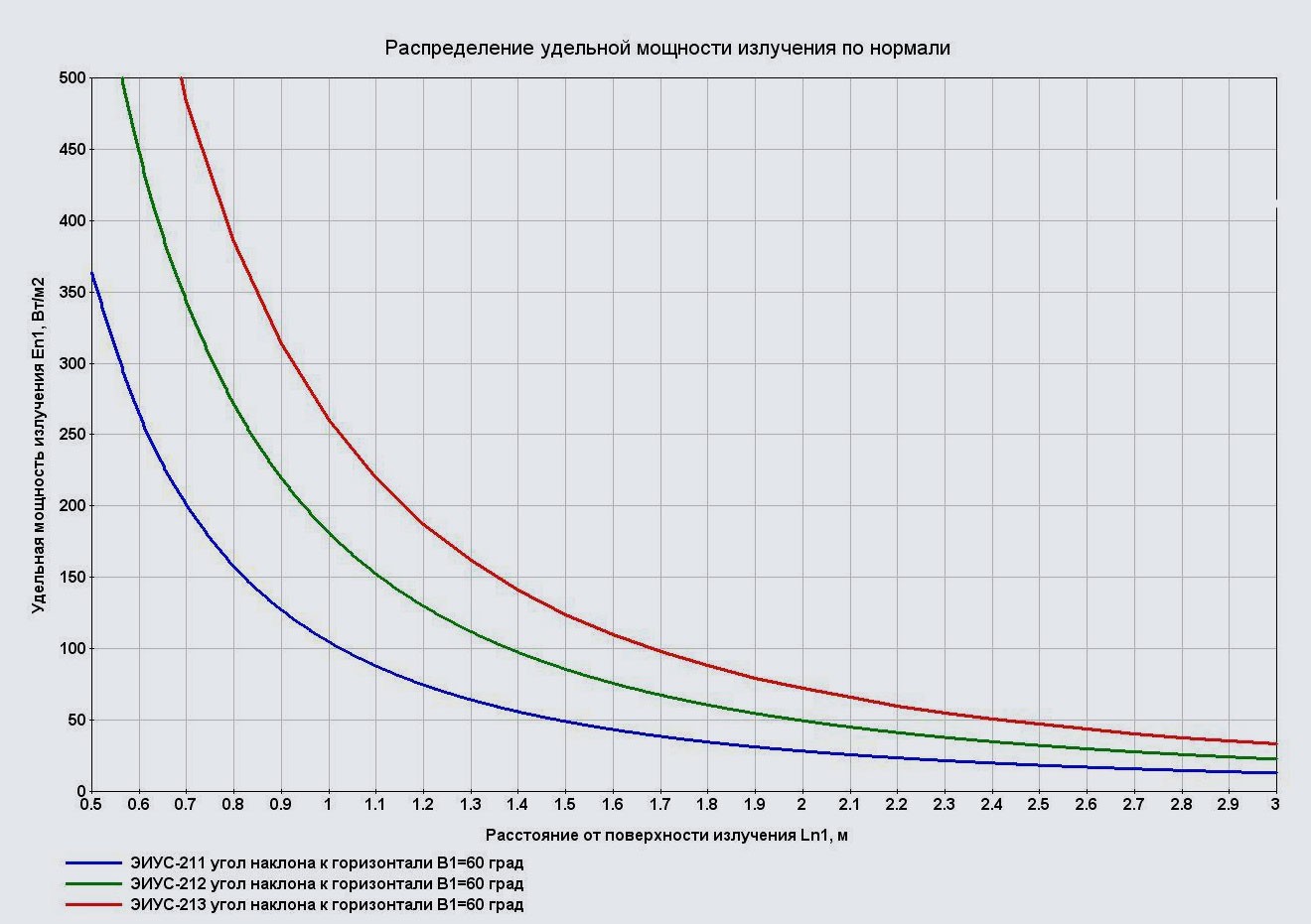
4) In accordance with mode 1 of heating, we take the normalized permissible specific power of IR heating of the worker's head, equal to no more than 60 W / m2... According to the graphs of the distribution of the specific radiation power along the normal for each brand of the EIUS heater, we determine the values En1, W / m2 on distance Ln1 = 1.87 m at the angle of inclination of the reflector to the horizontal β1 = 30 °: for EIUS-211 as standard En1 = 28 W / m2, for EIUS-212 En1 = 48 W / m2, for EIUS-213 En1 = 65 W / m2.
5) Analysis of certain values of the specific radiation power at the level of the worker's head shows: the use of the EIUS-211 heater will provide only half of the permissible heating power, the use of the EIUS-213 heater will slightly exceed the permissible power, but will allow to ensure the maximum permissible heating, if, for example, increase the distance Ln1 up to 2.1 m, the EIUS-212 heater will be used with some underheating relative to the maximum permissible specific heating power, while the heating efficiency can be increased to a maximum, for example, by reducing the distance Ln1 up to 1.7 m.
Example 2.
Solution of the problem, inverse to example 1. It is required to determine the minimum allowable distance from the wall to the workplace A1, m and the optimal angle of inclination of the reflector to the horizontal β1, deg. when installed on a wall heater EIUS-212 in the basic configuration at a height H1 = 2.2 m. The heating mode is one-sided frontal, with the worker's head hitting the area of the directed beam flux (see mode 1 in the table). The average height of an employee is assumed to be B1 = 1.75 m.
1) We draw up a heating scheme according to mode 1, taking into account the design parameters of the EIUS-200 heaters: A2 = 75 mm, Ln0 = 85 mm, α1 = 70 ° (see figure 2). With the optimal heating option, the central axis of the radiant flux (central normal to the radiation surface) should pass approximately through the middle of the body in height and at the same time B2 = (0,5 — 0,6) ⋅ B1... For calculations we accept B2 = 0.55 ⋅ B1, B2 = 0.9625 m.
2) In accordance with heating mode 1, we take the normalized permissible specific power of IR heating of the worker's head, equal to no more than 60 W / m2... According to the graph of the distribution of the specific radiation power along the normal for the EIUS-212 heater, we determine the distances Ln1, m at which En1 = 60 W / m2 for angles of inclination of the reflector to the horizontal β1 = 30 ° and β1 = 60 °: Ln1 = 1.65 m and Ln1 = 1.80 m... For subsequent calculations, we take the average value Ln1 = 1.725 m.
3) To calculate the value A1, m we use the formula (2) of the previous example 1:

A1 = 0.82 m.
4) Determine the optimal angle of inclination of the reflector to the horizontal β1, ° from expression (1) of the previous example 1:

β1 = 35.3 °
Example 3.
For the problem from example 2, it is required to determine the width (radius Rn1, m) zones of effective heating at a workplace located at a distance A1, m from a wall with a heater (see figure 4). Determine the width of the effective heating zone for heaters EIUS-211 and EIUS-213.
1) For the EIUS-212 heater, the effective heating zone is determined by the imposition of volumetric ray fluxes from each radiator (see Figure 4). According to the table "Technical characteristics of electric heaters EIUS-212" on the corresponding page of the site, we take the distance between the centers of the emitters Lm1= 270 mm and the opening angle of the ray flux at the exit from the reflector α1 = 70 °... Expression for calculating the length of the overlapping zone of ray fluxes Lsp1, m in plan at a distance A1, m from the wall will take the form:

Lsp1 = 1.61 m.
2) The value of the radius of the effective heating zone Rn1, m is determined by the formula:

Rn1 = 1.13 m.
3) For heaters EIUS-211 and EIUS-213, the radius of the effective heating zone is formed by a central radiator. In this case:
Rn1 = 1.26 m.
Example 4.
It is required to select an EIUS heater and determine the optimal height of its installation on the wall for one-sided frontal directional heating from a height of less than 1.8 m when the radiant flux hits mainly the worker's torso (see mode 2 of Table 2). In this case, the angle of inclination of the reflector to the horizontal is β1 = 45 °, the distance from the worker in the center of the workplace to the wall with the heater is A1 = 1.5 m, the average height of the employee is taken equal B1 = 1.75 m.
Table 1. Indicators of the microclimate of industrial premises equipped with SLO
| Temperature of air, environment ° С | SanPiN 9-80 RB 98 [3] GOST 12.1.005-88 [5] Intensity of thermal radiation, W / m2, no more, with the irradiated surface of the body 50% and more | SP 2.2.1.1312-03 [4] | ISO 7726: 1998 [6], formula (1), W / m2 | |
|---|---|---|---|---|
| Intensity of thermal irradiation of the head, W / m2, no more | Intensity of thermal irradiation of the body, W / m2, no more | |||
| 0 | - | - | - | 153 |
| 5 | - | - | - | 132 |
| 10 | - | - | - | 110 |
| 11 | - | 60 | 150 | 106 |
| 12 | 35 | 60 | 125 | 101 |
| 13 | 60 | 100 | 97 | |
| 14 | 45 | 75 | 92 | |
| 15 | 30 | 50 | 87 | |
| 16 | 15 | 25 | 83 | |
| 20 | - | - | 63 | |
| 25 | - | - | - | 38 |
| These regulatory documents are given for the period of an 8-hour work shift in relation to a person wearing a set of clothing with thermal insulation (thermal resistance) |
||||
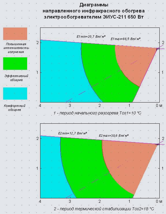
Thus, depending on the ambient temperature, electrical power and design of the heater, as well as on the normal distance from the radiation surface to the heating object (see the section "Infrared radiation characteristics - engineering applications"), it is possible to distinguish three zones of radiant heating in a room. equipped with an SLO: a zone of increased intensity of thermal irradiation at E1 > E1max, effective heating zone at E1min ≤ E1 ≤ E1max, as well as a zone of comfortable, but insufficient heating at E1 <E1min.
It should be noted that the above division into zones (see Figure 2), calculated by formulas (2-3) taking into account expression (1), is necessary for subsequent calculations when the heater is turned on for the first time, as well as when the SLO enters the specified mode of maintaining the temperature in room. As the room temperature rises, the boundaries E1max before E1min will shift towards lower values of ?1 and it is important to locate heating objects (workers, equipment, etc.) in the room so that they are constantly in the effective heating zone, or in the comfortable heating zone near the border of the zone.
To calculate the distribution of heating zones when using SLO based on EIUS-211 electric heaters, we will use the data in Table 2. We accept the initial temperature in the room Tos1 = 10 ° C, room temperature after warming up (with thermal stabilization) Tos2 = 18 ° C and using formula (1) we calculate the values of the limiting intensity of thermal radiation Eip1 = 111.4 W / m2, Eip2 = 73.8 W / m2 Using formulas (2) and (3), we calculate the boundary values of the irradiation zones: E1max = 66.5 W / m2, E1min = 12.7 W / m2 — для периода термической стабилизации.
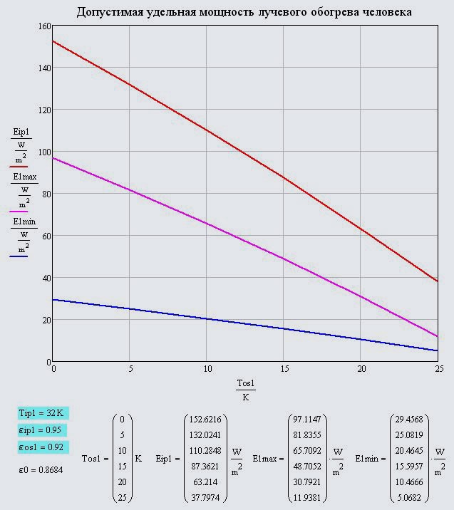
Table 2. Technical characteristics of IR electric heaters EIUS-211
| Indicator name | Electric power of TSC-101 emitter | ||||
|---|---|---|---|---|---|
| 250 | 400 | 500 | 650 | 1000 | |
| Dimensions of the emitter in plan, calculated area and emissivity (emissivity) of the radiation surface | 245x60 mm, Fiz1 = 170.9 cm², ε1 = 0.96 | ||||
| Dimensions of the reflector-reflector in plan, the reduced dimensions of the central elementary radiation surface and the reduced radius of the radiation surface | Lot1 = 250 mm, Bot1 = 100 mm L1 = 100 mm, B1 = 100 mm, R1 =  = 56.42 mm = 56.42 mm |
||||
| The assumed volumetric opening angle of the beam flux at the exit from the reflector | α1 = 68-72 ° | ||||
| Radiating surface temperature | 400 | 490 | 540 | 600 | 720 |
| The coefficient of emission of electrical energy into the energy of directional infrared radiation (beam efficiency) when the reflector is placed at an angle of 27-30 ° downward relative to the horizontal, the degree of blackness of the background and the ambient temperature (averaged) | 69,7 | 73,0 | 79,5 | 81,3 | 84,9 |
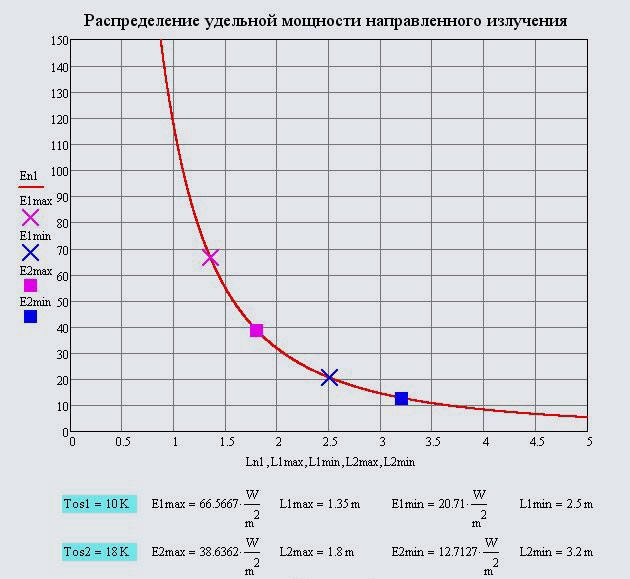
Calculation of the distribution of the specific power of irradiation along the normal to the radiating surface of the electric heater En1, W / m² we produce according to the dependence

Where
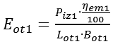
- specific radiation power reduced to the area of the reflector-reflector, W / m2, Ln1 Is the current value of the distance from the radiation surface, m. In the calculations by formula (4), the value of the volumetric opening angle of the ray flux at the exit from the reflector-reflector is taken α1= 70 °.
Figure 3 shows the obtained graph of the distribution of the specific radiation power along the normal to the emitting surface. The dots mark the obtained boundary distances of the heating zones: L1max = 1.35 m, L1min = 2.5 m, for the initial warm-up period, L2max = 1.8 m, L2min = 3.2 m, for the period of thermal stabilization.
Figure 4 shows the heating diagrams of a 4 m long room with a ceiling height of 2.5 m, which is equipped with an SLO in the form of an EIUS-211, placed on the wall at a height of 1.8 m with the direction of the reflector-reflector diagonally of the room at an angle of 27-30 ° downward. in relation to the horizontal. The highlighted volumetric arrangement of heating zones on the diagrams with the possibility of changing the location of the electric heater and the direction of the radiant flux makes it possible to find the optimal location of the AO and objects of heating.
It should be noted that the above calculations and, on their basis, the zoning of the room according to the heating modes are valid for radiant irradiation of 50% and more of the human body. The optimal construction of the AO in this case determines the presence of two or more heaters located diametrically throughout the room or in a dedicated heating zone. In order to reduce the size of the zone of increased radiation intensity when thermal stabilization is achieved, the electric heater must be equipped with a stepped heating power switch.
The developed technique makes it possible to estimate the intensity of irradiation, for example, both at floor level and at the level of a person's head as one approaches the heater. Obviously, the installation of infrared heaters on the ceiling with the supply of radiation from top to bottom for rooms with ceilings with a height of 2.5-4 m will always create a radiation intensity of the human head much higher than the rest of the body. In this case, the head, as a rule, will be in a zone of increased radiation intensity, which does not allow to withstand the current radiation standards and sharply increases the intolerance of radiation heating by workers.
Literature:
1. Рабко А.Е. Инфракрасные керамические излучатели и электрообогреватели НОМАКОНтм/ А.Е. Рабко и др. // Электроника инфо. — 2011. — №5. — С.26-29.
2. Рабко А.Е. Отопление помещений инфракрасными электрообогревателями НОМАКОНтм / А.Е. Рабко и др. // Электроника инфо. — 2013. — №9. — С.45-48.
3. SanPiN 9-80 RB 98. Hygienic requirements for the microclimate of industrial premises.
4.SP 2.2.1.1312-03. Hygienic requirements for the design of newly built and reconstructed industrial enterprises. Appendix 2.
5.GOST 12.1.005-88. Occupational safety standards system. General sanitary and hygienic requirements for the air in the working area.
6.ISO 7726: 1998. Ergonomics of the thermal environment. Instruments for measuring physical quantities.