


Description
The body of the emitters is made of a refractory ceramic material covered with a protective ceramic glaze.
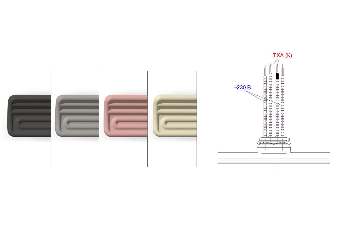
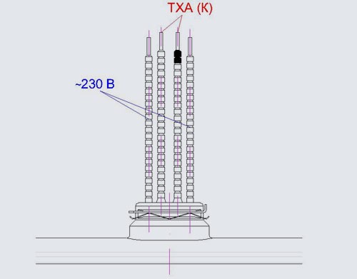
Inside the ceramic body there is an electric spiral made of a multicomponent Fe-Cr-Al alloy (superfechral GS SY) with alloying elements (version 1) or an electric spiral and a temperature sensor of the emitting surface in the form of a thermocouple TXA (chromel-alumel) type "K" with contact leads (version 2).
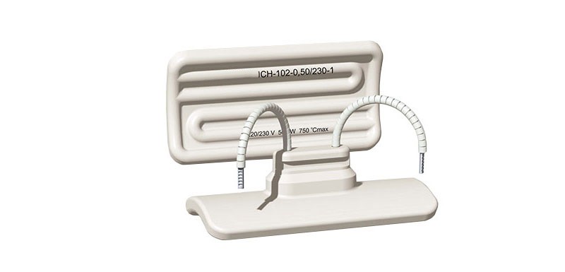
The concave shape of the radiation surface makes it possible to better scatter infrared rays from the rear surface of the emitter body with their subsequent focusing by a reflector-reflector on the heated surface. This reduces heat loss from heating the reflector, and also minimizes the dispersion of radiation energy when the emitter moves away from the heated surface, which makes it possible to increase the distance and reduce the number of emitters per unit of heating area.
The distance from the radiator to the heating surface in technological processes is, as a rule, at least 100-250 mm.
The radiators of the IKN-100 series allow generating infrared radiation at the maximum permissible temperature of the radiating surface plus 750 ° C and a specific surface energy of radiation up to 6.0 W /cm2.
The service life of the emitters is at least 5 years. Mean time between failures is: for emitters with specific surface radiation energy from 4.1 to 6.0 W / cm² (650-750 ° С) not less than 5000 h, with radiation energy from 1.95 to 4.1 W / cm² (500-650 ° C) not less than 7000 h, with radiation energy up to 1.95 W / cm2 - not less than 10000 h.
-

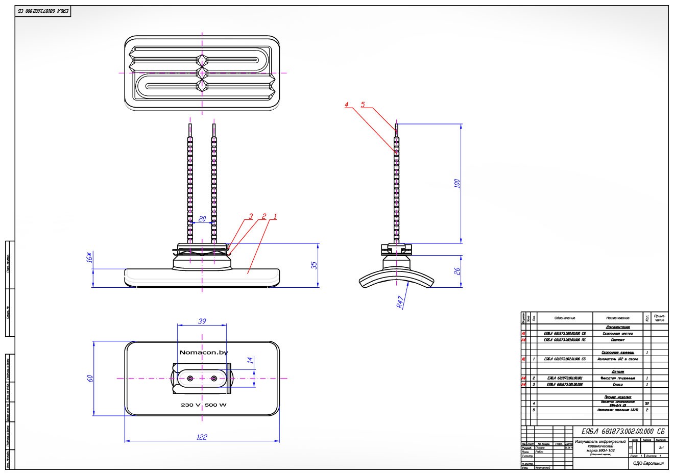
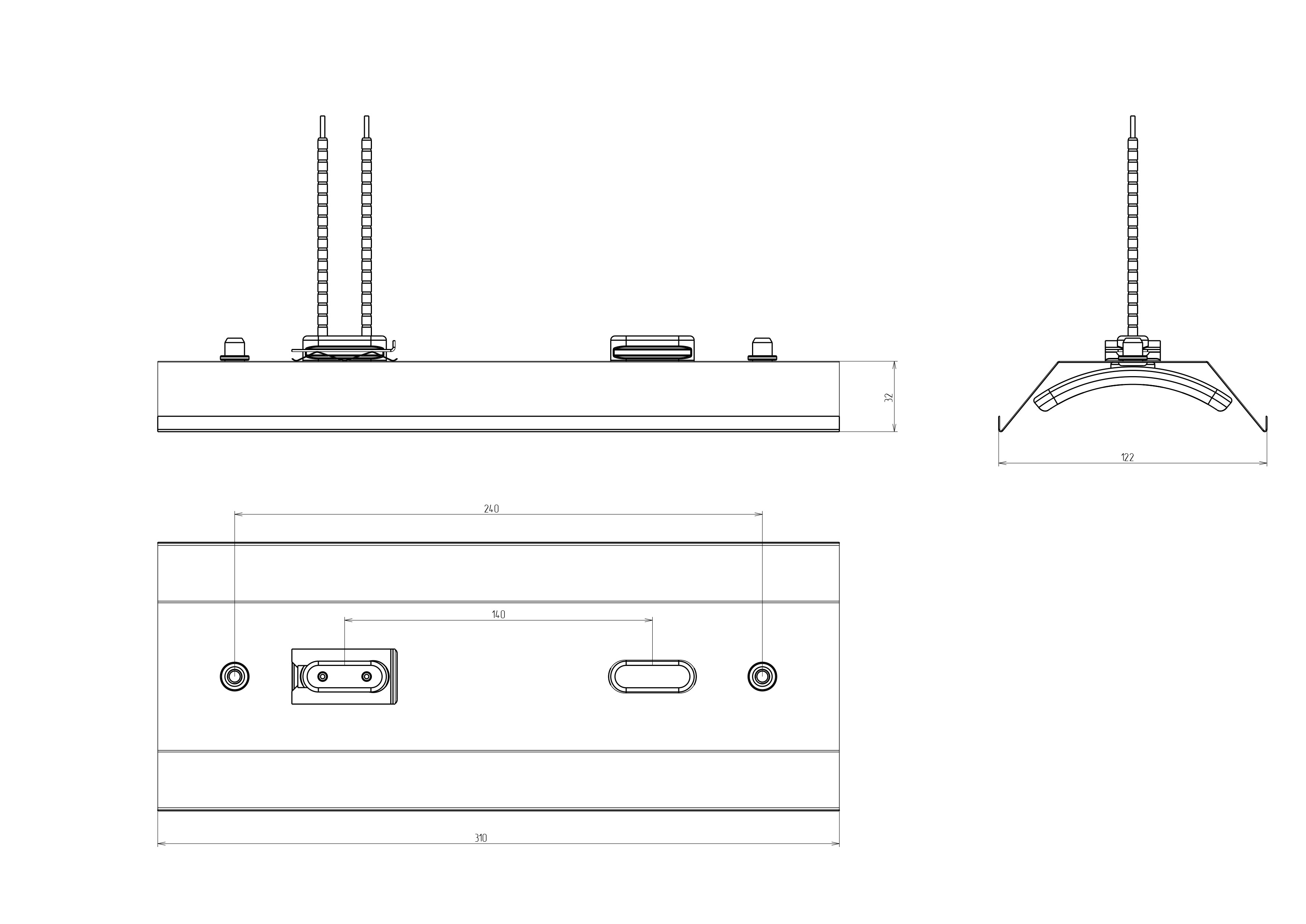
Overall and installation dimensions -
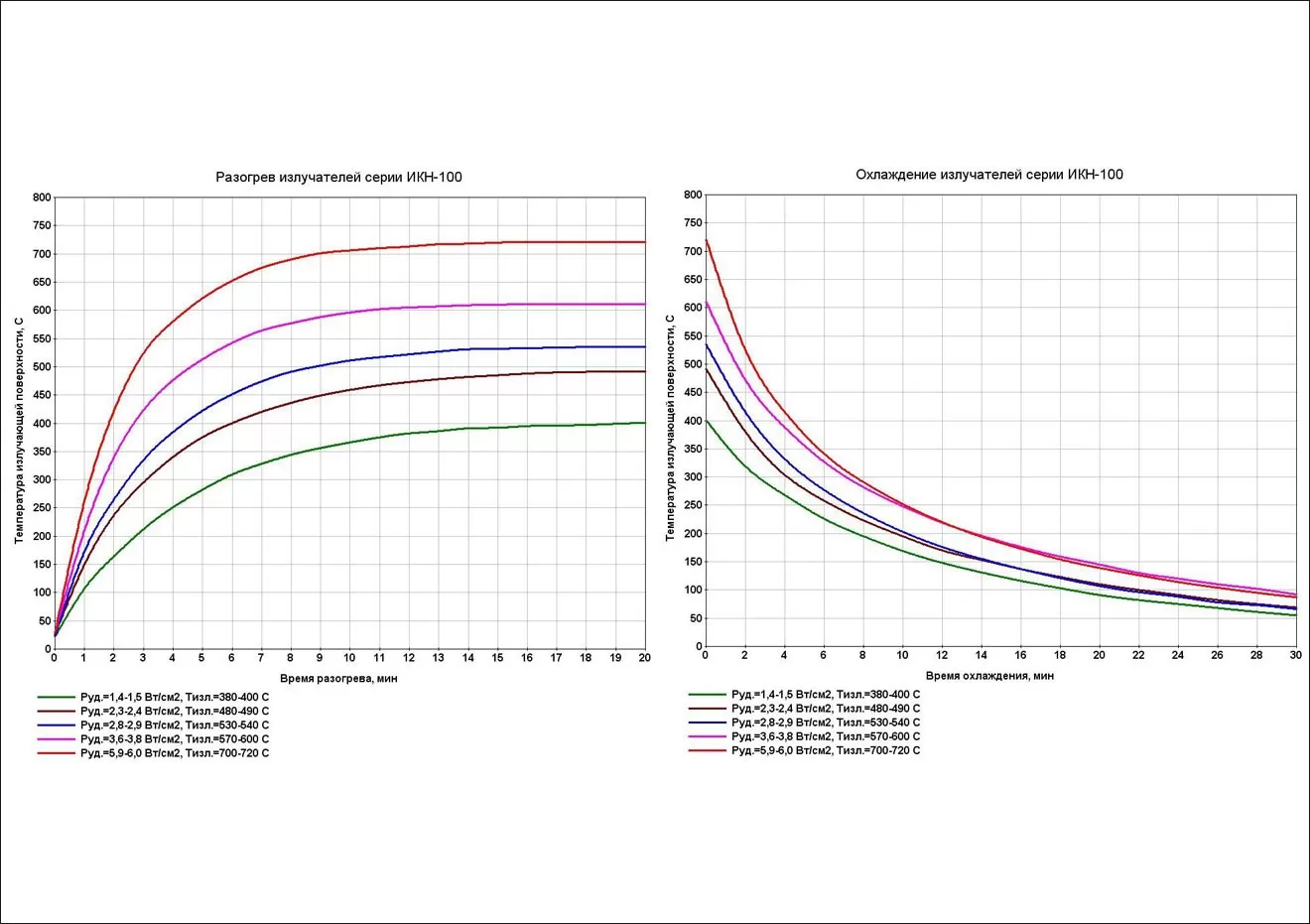
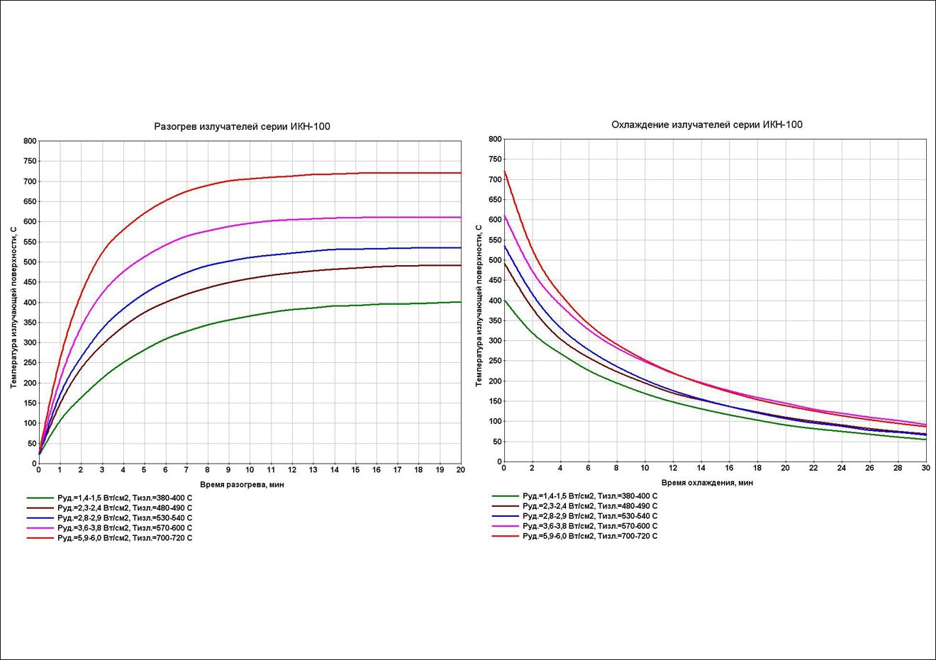
Heating and cooling diagrams -
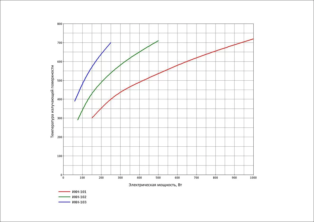
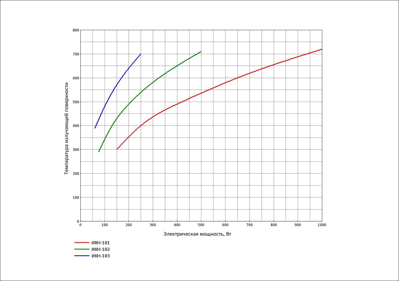
Radiating surface temperature -

Additional options
Additional options
Electrical power and supply voltage
- on request, it is possible to produce a batch of emitters with a different electric power and supply voltage from 127 to 400 V, not exceeding the limit values for a given brand of emitter.
Increasing the length of electrical wires
- cable-leads for connecting the radiator to the mains
Color
- gray, black, pink, beige, yellow, etc. as agreed with the customer
Built-in temperature control temperature sensor:
- thermocouple type TXA (K) is built into the body of the emitter (version 2) to control the temperature of the emitting surface during heating.
Specifications
| Indicator name | Electric power, W | ||||
|---|---|---|---|---|---|
| 125 | 200 | 250 | 325 | 500 | |
| Electrical power per unit of radiation surface (2), W / cm² | 1,5 | 2,4 | 2,9 | 3,8 | 5,9 |
| Radiating surface temperature(1), ° С | 390 | 480 | 530 | 600 | 710 |
| Specific surface radiation energy(1), W / cm² | 1,05 | 1,75 | 2,26 | 3,16 | 5,08 |
| Effective wavelength range of infrared radiation, microns | 2,25-10,6 | 2,0-9,35 | 1,85-8,8 | 1,7-8,10 | 1,5-7,15 |
| Wavelength of the maximum spectral radiation intensity, μm | 4,4 | 3,8 | 3,6 | 3,3 | 2,9 |
| Time to reach operating temperature when switched on(1), min, not more | 20 | 18 | 16 | 14 | 12 |
| Maximum permissible temperature of the emitter body, ° С | 750 | ||||
| AC supply voltage (50 Hz), V | 220/230 | ||||
| Working hours | Long-term under the supervision of GOST 16617 | ||||
| Dimensions of the radiating surface (length x width), mm | 122×60 | ||||
| Estimated radiation surface area, cm² | 85,1 | ||||
| Curb weight, g, not more | 125 | ||||
| ¹ - achieved in the body of the EIUS-211 electric heater (2 emitters are installed) at an ambient temperature of +18 to +25 ° С
² - diagrams of heating and cooling of IKN-102 emitters are given for temperatures of the radiating surface Toutl. , ° С, corresponding to the specified tabular values of electric power per unit of radiation surface Рbeats , W / cm² |
|||||
Designation when ordering
Infrared ceramic emitter TU BY 190454267.004-2015
TSC-102—0,5/230—1
|
TSC-1 |
emitter model designation - with a concave emitting surface (models 1, 2 and 3 are available). |
|
02 |
обозначение модификации — модификация с размером 122х60 мм (выпускаются модификации 01, 02, 03, 04). |
|
0,5 |
rated power consumption, kW. |
|
230 |
rated value of AC supply voltage, 220/230 V, 50 Hz. |
|
1 |
1-without thermocouple, 2-with thermocouple. |
Completeness
Ceramic emitter assembly(1) - 1 PC.
Spring latch - 1 pc.
Mounting bracket - 1 pc.
Passport, application manual(2) - 1 PC.
Packing box - 1 pc.
(1) - the brand of the emitter and the electric power are indicated on the ceramic body and on the packaging
(2) - upon delivery, one passport can be issued for several emitters from one batch
Directions for use
- Emitters as part of products must be operated in industrial, residential, public and domestic premises, provided that there are no chemically aggressive, fire and explosive substances in the environment. Climatic operating conditions UHL4 in accordance with GOST 15150 (closed heated and ventilated rooms, no pronounced condensation and moisture) at an ambient temperature from plus 1 to plus 40 ° C.
- Acceptance, installation and testing of emitters as part of the product is allowed by personnel who have studied their design and principle of operation, as well as safety rules.
- When accepting the emitter for installation, it is necessary to conduct its external examination for damage to the ceramic body and insulators of electrical current-carrying wires. If necessary, clean the housing from dirt.
- Emitters of version 1 have on the base of the ceramic housing two contact leads with current-carrying wires for connecting to the mains, as shown in Figure 1. Emitters of version 2 with a built-in temperature sensor (TCA thermocouple of the "K" type) have two additional contact leads in the center of the base for connection to a measuring device or thermostat (see Figure 2). Designation of poles for connection to the measuring device: black ceramic insulator at the end of the contact wire corresponds to the input of the device "minus".
- The diagram of installation and connection of the emitter to the mains is shown in Figure 1. Emitter 1 is inserted with a mounting base with current supply wires into a 40x15 mm hole in reflector 4, a spring clip 2 is installed on top of the reflector surface through the base 2. The fastening bracket 3 is installed in the slot of the base, compressing the spring clip and pressing the mounting surface of the emitter base 1 to the inner surface of the reflector 4. When properly installed, the emitting surface should be parallel to the inner surface of the reflector 4.
- During operation, it is necessary to regularly check the ceramic body of the emitter for damage and contamination. Accumulation of dust and other contaminants on the body of the emitter and on the reflector can lead to a fire hazard when the emitter is turned on. It is also necessary to regularly check that all electrical connections are secure and that the electrical insulation is secure.
- The ceramic body of the emitter is non-separable and cannot be repaired. If a defect is found during the warranty period, the product must be replaced by the manufacturer through the point of sale where it was purchased.
Safety requirements
- The emitter must be installed in compliance with the electrical installation rules and these instructions for use.
- When installing the emitter, it is necessary to fulfill all the conditions for connection, as well as to ensure reliable fastening of the emitter body to the reflector surface, fastening of the current supply wires and the electric cable.
- IT IS FORBIDDEN to install and turn on emitters with a damaged (cracked) ceramic surface, with cracked ceramic insulators on the lead wires, with damaged lead wires and lugs.
- IT IS FORBIDDEN to exceed the rated supply voltage of the emitter due to possible overheating of the emitting surface above the maximum permissible temperature.
- IT IS FORBIDDEN to use emitters in closed heating systems: the space in front of the emitting surface must always be open for the output of infrared radiation (removal of thermal energy), the rear side of the reflector and cable channels must be equipped with ventilation slots and must not be insulated with heat-insulating materials. Otherwise, an uncontrolled decrease in heat removal by infrared radiation and thermal convection can lead to overheating of the radiating surface and a fire hazard.
manufacturer's warranty
- The manufacturer guarantees the compliance of the product with the requirements of the current regulatory documentation, subject to the conditions of transportation, storage, installation and operation.
- Shelf life is 2 years from the date of manufacture.
- The warranty period is 12 months from the date of commissioning (sale), or from the date of manufacture in the absence of the date of sale.
- During the warranty period, the consumer has the right to replace the faulty emitter through the point of sale from which it was purchased.
- The warranty does not apply to emitters without a passport with a mark of sale, incomplete, having mechanical damage or other signs of violation of the rules of transportation, storage and operation.