


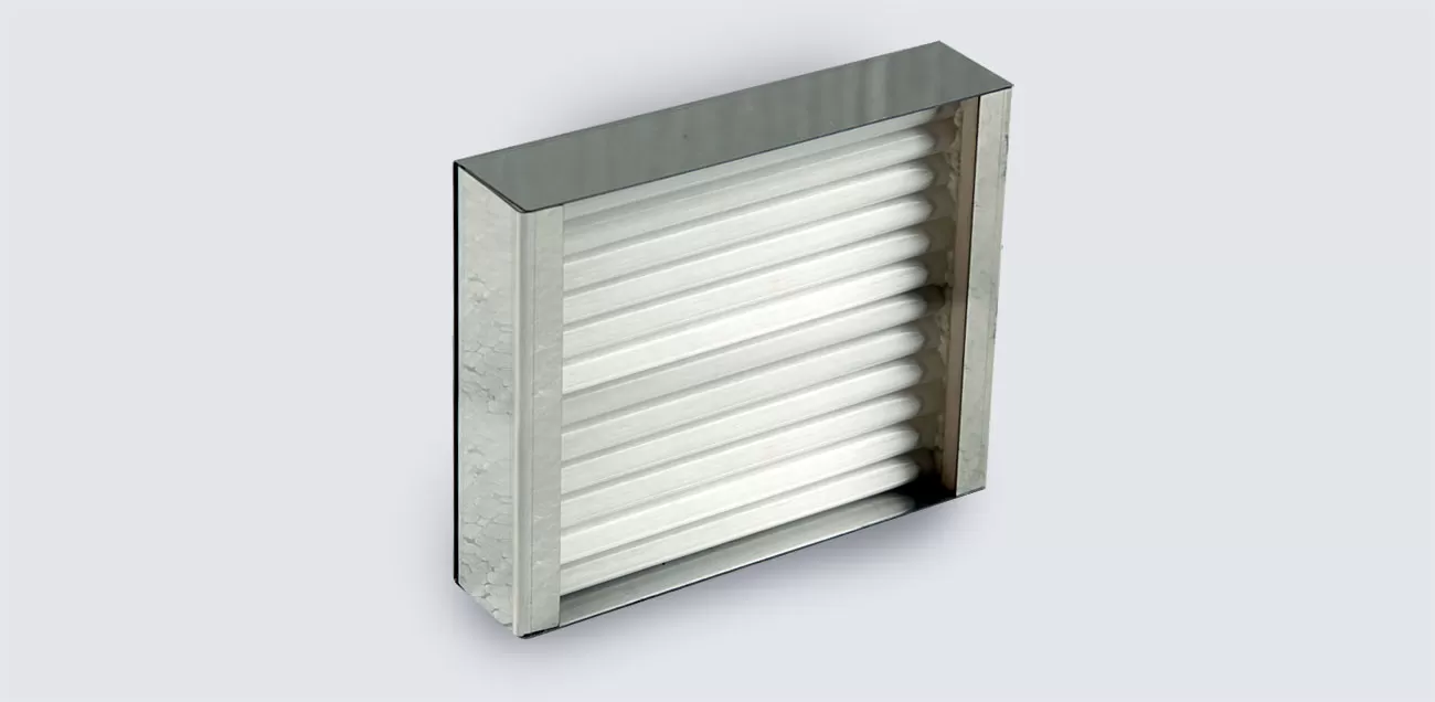
Description
The emitter housing is made of heat-resistant stainless steel. The casing contains a thermal protection shield made of polished stainless steel with thermal insulation and quartz glass emitting tubes (emitters).
Inside the quartz tubes there is an electric spiral made of a multicomponent Fe-Cr-Al alloy (superfechral GS SY) with alloying elements (version 1) or an electric spiral and a temperature sensor of the emitting surface in the form of a thermocouple TXA (chromel-alumel) type "K" with contact leads (version 2).
Due to the minimum warm-up time when turned on and fast cooling when turned off, the TSC-400 emitters are recommended for use in infrared heating processes that are often interrupted by turning on and off: thermoforming, heat shrinkage, local heating in the "thermal shock" mode, when drying in batch chambers, in mobile car dryers, etc. TSC-400 is also used in cyclic heating processes with a programmable specific radiation power, for example, in infrared soldering stations.
The distance from the radiator to the heating surface in technological processes is, as a rule, at least 100-250 mm.
The IRN-400 series emitters allow generating infrared radiation at the maximum permissible temperature of the radiating surface of quartz tubes plus 780 ° C and a specific surface radiation energy of up to 6.0 W/cm2.
The maximum permissible temperature of the emitter body when installed in the heating panel is no more than plus 550 ° С.
The service life of the emitters is at least 5 years. Mean time between failures is: for emitters with specific surface radiation energy from 3.5 to 6.0 W / cm² (650-780 ° С) not less than 5000 h, with radiation energy up to 3.5 W / cm2 (not more than 650 ° С) - not less than 7000 h.
-
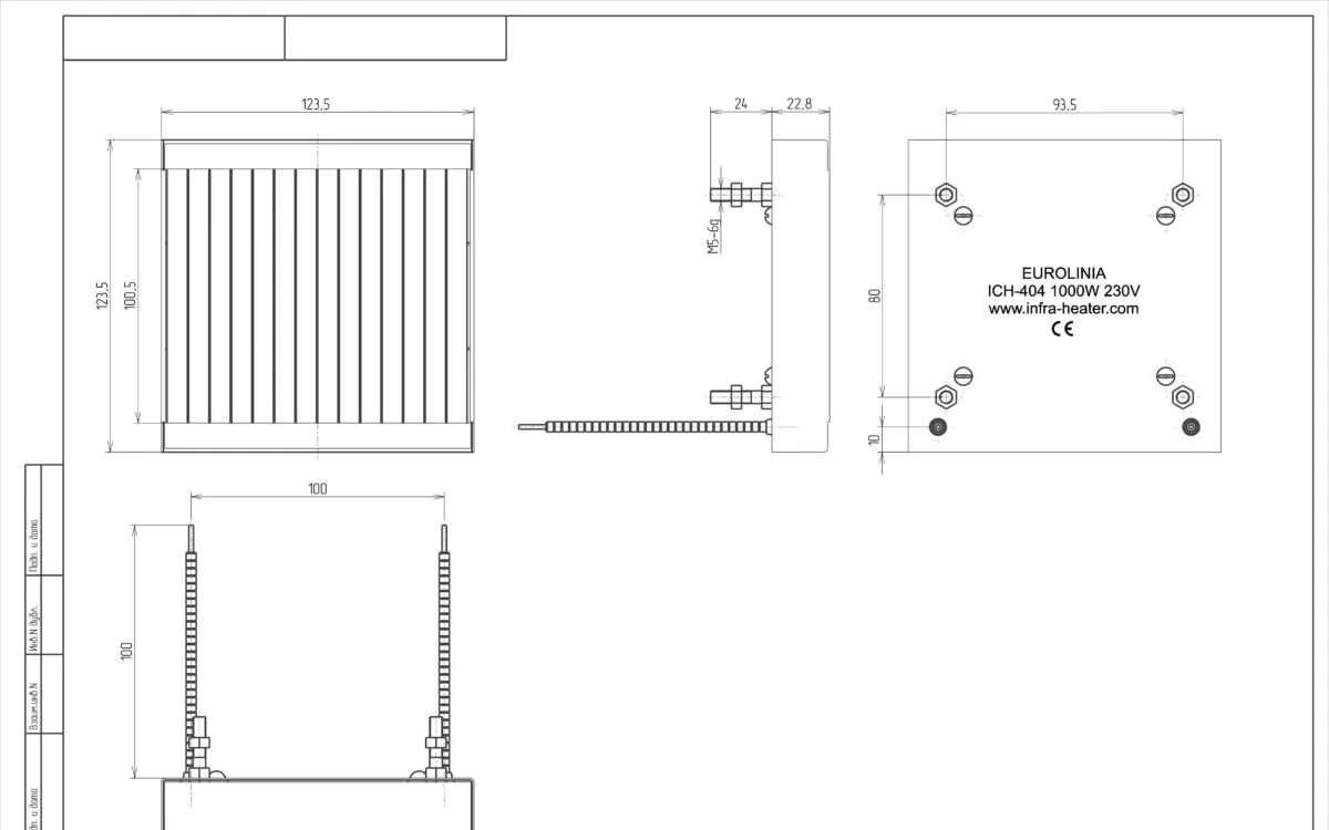
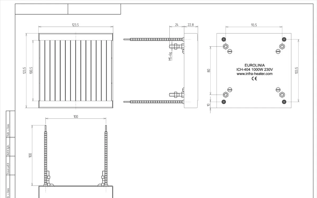
Overall and installation dimensions -
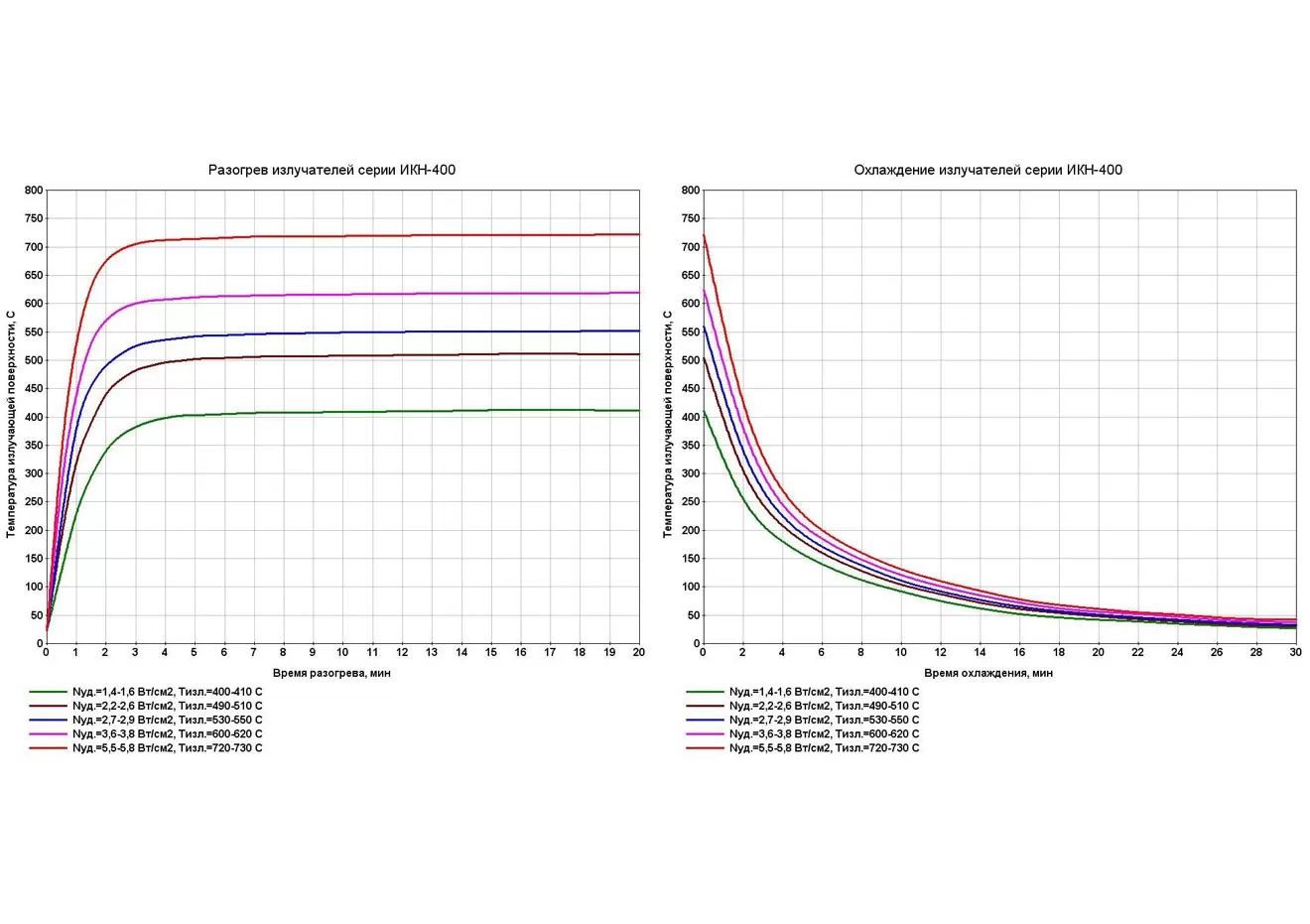
Heating and cooling diagrams -
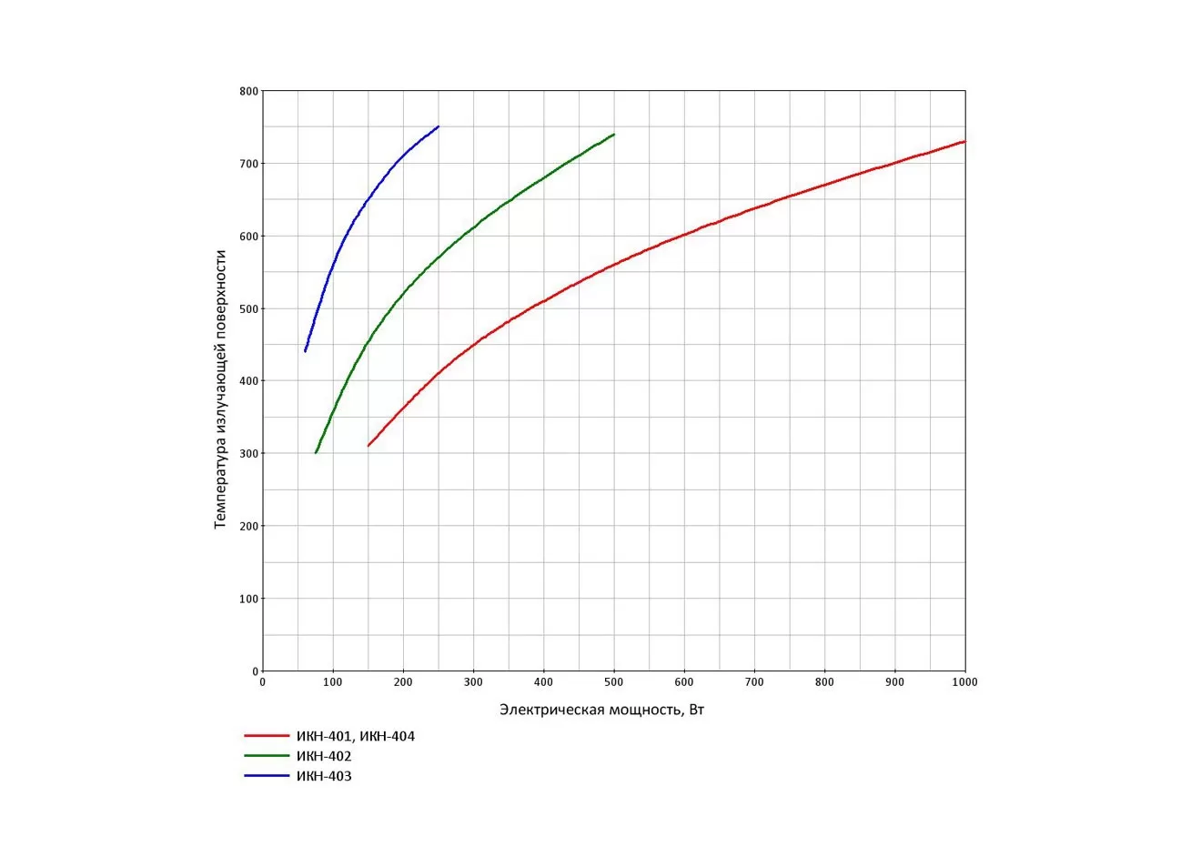
Radiating surface temperature -
Additional options


Additional options
Electrical power and supply voltage
- upon agreement with the consumer, on request, it is possible to produce a batch of emitters with a different electrical power and supply voltage from 127 to 400 V, not exceeding the limit values for a given brand of emitter.
Increasing the length of electrical wires
- cable outputs for connecting the emitter to the mains.
Built-in temperature control temperature sensor
- thermocouple type TXA (K) is built into the body of the emitter (version 2) to control the temperature of the emitting surface during heating.
Specifications
| Indicator name | Electric power, W | ||||
|---|---|---|---|---|---|
| 250 | 400 | 500 | 650 | 1000 | |
| Electrical power per unit of radiation surface (2), W / cm² | 1,4 | 2,4 | 2,7 | 3,6 | 5,5 |
| Radiating surface temperature(1), ° С | 400 | 500 | 540 | 610 | 720 |
| Specific surface radiation energy(1), W / cm² | 1,00 | 1,68 | 2,11 | 2,93 | 4,68 |
| Effective wavelength range of infrared radiation, microns | 2,15-10,5 | 1,95-9,2 | 1,7-7,95 | 1,8-8,65 | 1,5-7,05 |
| Wavelength of the maximum spectral radiation intensity, μm | 4,3 | 3,8 | 3,6 | 3,3 | 2,9 |
| Time to reach operating temperature when switched on(1), min, not more | 5 | 5 | 5 | 4 | 3 |
| Maximum permissible temperature of the radiation body, ° С | 780 | ||||
| AC supply voltage (50 Hz), V | 220/230 | ||||
| Working hours | Long-term under the supervision of GOST 16617 | ||||
| Dimensions of the body (length x width), radiation zones in plan, mm | 124x120, 119x104 | ||||
| Estimated radiation surface area, cm² | 183,0 | ||||
| Curb weight, g, not more | 380 | ||||
| ¹ - achieved in the case of an infrared panel electric heater NOMACONTM EIP-212 at an ambient temperature of +18 to +25 ° С ² - diagrams of heating and cooling of IKN-404 emitters are given for temperatures of the radiating surface Toutl. , ° С, corresponding to the specified tabular values of electric power per unit of radiation surface Рbeats , W / cm² |
|||||
Designation when ordering
Infrared ceramic emitter TU BY 190454267.005-2015
TSC-404—1,0/230—1
|
TSC-4 |
emitter model designation (infrared quartz emitter) |
|
04 |
обозначение модификации (модификация с размером корпуса 125х125 мм, всего выпускаются модификации с размером корпуса 01, 02, 03 и 04) |
|
1,0 |
rated power consumption, kW. |
|
230 |
rated value of AC supply voltage, 220/230 V, 50 Hz. |
|
1 |
1-without thermocouple, 2-with thermocouple. |
Completeness
Quartz infrared emitter, assembled(1) - 1 PC.
Fastening nut M5 GOST 5915-70 - 2 pcs.
Fastening washer 5L GOST 6402-70 - 2 pcs.
Passport, application manual(2) - 1 PC.
Packing box - 1 pc.
(1) - the brand of the emitter and the electric power are indicated on the body and on the packaging
(2) - upon delivery, one passport can be issued for several emitters from one batch
Directions for use
- Emitters as part of products must be operated in industrial, residential, public and domestic premises, provided that there are no chemically aggressive, fire and explosive substances in the environment. Climatic operating conditions UHL4 in accordance with GOST 15150 (closed heated and ventilated rooms, no pronounced condensation and moisture) at an ambient temperature from plus 1 to plus 40 ° C.
- Acceptance, installation and testing of emitters as part of the product is allowed by personnel who have studied its structure and principle of operation, as well as safety rules.
- When accepting the emitter for installation, it is necessary to conduct its external inspection for damage to the metal case, quartz tubes and electric spirals, as well as ceramic insulators of electric current-carrying wires. If necessary, clean the case from dust and dirt.

- Emitters of version 1 have two contact leads on the metal casing with current-carrying wires for connecting to the mains, as shown in Figure 1. Emitters of version 2 with a built-in temperature sensor (TCA thermocouple of the "K" type) have two additional contact leads in the center for connecting to the measuring device or thermostat (see Figure 2). Designation of poles for connection to the measuring device: black ceramic insulator at the end of the contact wire corresponds to the input of the device "minus".

- The diagram of installation and connection of the emitter to the mains is shown in Figure 1. Emitter 1 is inserted with fixing pins into holes with a diameter of 6 mm in the case of an electric heater or heating panel 2 and is attached to it using nuts 3 with washers 4. In this case, the conductive wires 5 pass through the corresponding holes with a diameter 6-8 mm panel 2. The connecting dimension between the fixing pins of the housing L1, as well as the dimensions of the arrangement of conductive wires L2 and L3, are given on the drawing of the radiator on the website page for the given radiator brand.
- During operation, it is necessary to regularly check the surface of the quartz tubes of the emitter for damage and contamination. Accumulation of dust and other contaminants on the housing and on the quartz tubes can lead to a fire hazard when the emitter is turned on. It is also necessary to regularly check that all electrical connections are secure and that the electrical insulation is secure.
- The quartz emitter is non-separable and cannot be repaired. If a defect is found during the warranty period, the product must be replaced by the manufacturer through the point of sale where it was purchased.
Safety requirements
- Installation of the emitter must be carried out in compliance with the rules for the installation of electrical equipment (PUE) and this manual for use.
- When installing the emitter, it is necessary to fulfill all the conditions for connection, as well as to ensure reliable fastening of the emitter body to the surface of the electric heater, fastening of the current supply wires and the electric cable.
- Is prohibited install and turn on emitters with a damaged case, with split quartz tubes, with broken ceramic insulators on the current supply wires, with damaged current supply wires and lugs.
- Is prohibited exceed the rated supply voltage of the emitter due to possible overheating of the emitting surface above the maximum permissible temperature plus 780 ° C, or overheating of the metal housing of the emitter above plus 550 ° C.
- Is prohibited use radiators in closed heating systems: the space in front of the radiating surface must always be open for infrared radiation (heat energy removal), there should be ventilation slots between the back of the radiator body and the panel for the passage of cooling air, the outside of the radiator body must not be covered with heat-insulating material. Otherwise, an unregulated decrease in heat removal by infrared radiation and thermal convection can lead to overheating of the electric spiral and the radiating surface and a fire hazard.
manufacturer's warranty
- The manufacturer guarantees the compliance of the product with the requirements of the current regulatory documentation, subject to the conditions of transportation, storage, installation and operation.
- The shelf life is 2 years from the date of manufacture.
- The warranty period is 12 months from the date of commissioning (sale), or from the date of manufacture in the absence of the date of sale.
- During the warranty period, the consumer has the right to replace the faulty emitter through the point of sale from which it was purchased.
- The warranty does not apply to emitters without a passport with a mark of sale, incomplete, having mechanical damage or other signs of violation of the rules of transportation, storage and operation.