The physical nature of infrared heating
The physical essence of infrared heating is the transfer of thermal energy in the form of infrared radiation from the emitting surface of the radiation source directly to the heated object without heating the surrounding air. The main heating elements of this type of heaters are infrared emitters (hereinafter referred to as IR emitters, emitters), which are electrical resistance heating elements that generate infrared radiation when the ceramic emitting surface is heated by transferring thermal energy to it from a heated electric spiral built into the ceramic body.
The principle of operation of infrared heaters is based on their versatility and high efficiency: due to the specified characteristics of infrared radiation, people, objects and equipment, building structures located in the zone of operation of the heaters are heated and the surrounding air is practically not heated. As a result, additional energy costs are not required for heating the air in the volume of the room, which, during convective heating, heats up and accumulates under the ceiling above the living area. Thus, there is a real possibility of heating with infrared radiation with the creation of different temperature zones in one room, for example, additional local heating of workplaces in large industrial premises.
Thanks to the effective and safe heating of the human body with infrared radiation of a given wavelength and spectral intensity, ceramic emitters are widely used in infrared electric heaters for industrial and domestic purposes, as well as in thermal radiation systems for infrared saunas and physiotherapy installations. The possibility of rapid and uniform surface heating in various technological processes has led to the massive use of IR emitters in devices for heating and processing polymeric materials, in drying chambers for fabrics, printing products and wood from moisture and organic solvents, i.e. in those processes where materials and solvents absorb infrared radiation well in a given wavelength range, having an emissivity (emissivity) of at least 0.85-0.90.
Infrared characteristics
Infrared radiation is the portion of the solar spectrum that is directly adjacent to the red portion of the visible spectrum. The human eye is unable to see in this region of the spectrum, but we can perceive this radiation as radiant heat (see Figure 1). Infrared radiation has two important characteristics: the wavelength (frequency) of the radiation and the intensity of the radiation.
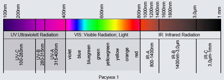
According to DIN 5031, depending on the wavelength, three regions of infrared radiation are distinguished: near IR-A (0.75-1.4 μm), middle IR-B (1.4 - 3.0 μm) and far IR-C ( 3.0-80 μm). Taking into account the physiological characteristics of humans, modern medicine characterizes these areas of the spectrum as follows (see Figure 2):
- wavelength 0.75-1.4 microns - radiation penetrating deep into the human skin (IR-A range);
- wavelength 1.4-3 microns - radiation absorbed by the epidermis and the connective tissue layer of the skin (IR-B range);
- wavelength over 3 microns - radiation absorbed on the skin surface (IR-C range).
In this case, the greatest penetration is observed in the range from 0.75 to 3 microns and this range is called the "window of therapeutic transparency" of radiant infrared heating of the human body.
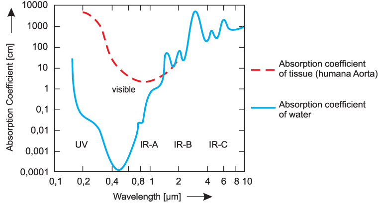
Figure 2 (original source - Journal of Biomedical Optics 12 (4), 044012 July / August 2007) shows the absorption spectra of infrared radiation for water and tissue of human organs, depending on the wavelength. It is noted that the tissue of the human body consists of water on 98% and this fact explains the similarity of the absorption characteristics of infrared radiation in the spectral range of 1.4-10 microns.
If we take into account the fact that water itself intensively absorbs infrared radiation in the range of 1.4-10 microns with peaks at wavelengths of 2.93, 4.7 and 6.2 microns (see Figure 2 and Yukhnevich G.V. Infrared spectroscopy of water, M, 1973), then the most effective for heating and drying processes should be considered infrared emitters, emitting in the middle and far infrared spectrum with a peak of radiation intensity in the wavelength range of 1.5-7.0 microns.
The total amount of energy emitted per unit time by a unit of emitting surface is called emissivity, or specific radiation energy IR emitter E, W / m2... Radiation energy depends on wavelength λ, μm and temperature of the emitting surface T, ° C and is an integral characteristic, since it takes into account the radiation energy of all wavelengths of a given spectral range of radiation.
Emissivity per wavelength interval dλ are called radiation intensity I, W / (m2• μm).

Integration of expression (1) makes it possible to determine the specific radiation energy based on the spectrum of radiation intensity determined either by calculation or experimentally I = f (λ) in the wavelength range from λ1 before λ2.

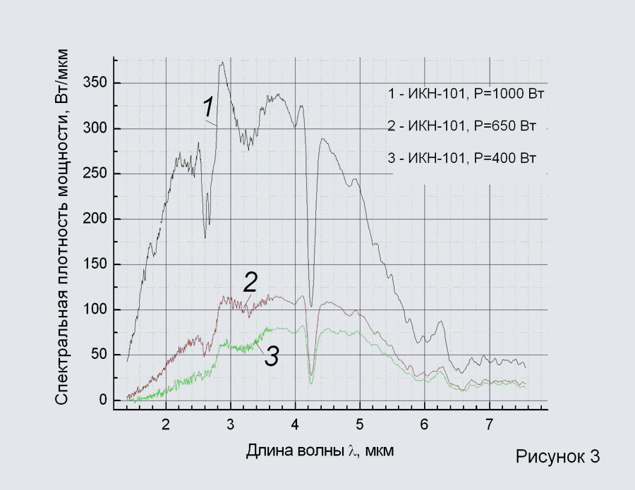
Figure 3 shows the spectra of the radiation intensity of infrared emitters NOMAKON TSC-101, obtained at various nominal electric power of the emitter, which is 1000 W, 650 W and 400 W. The emitters had a unified standard size of the radiating surface in plan, equal to 245x60 mm.
The tests were carried out at the Institute of Physics of the National Academy of Sciences of Belarus. The infrared radiation spectra were measured on an upgraded SDL-2 spectro-measuring complex (LOMO, St. Petersburg, USSR) using an MDR-23 registration monochromator. The distance from the ceramic emitters to the monochromator slit was 500 mm. A module from ORIEL INSTRUMENTS (USA) was used as a photodetector, the sensitivity of which did not depend on the radiation wavelength. With an increase in the power of the emitter and, accordingly, the temperature of the emitting surface, the radiation intensity increases, and the radiation spectrum shifts to the region of shorter wavelengths (Wien's displacement law)... In this case, the peak of the radiation intensity (not less than 80 % spectrum) falls on the wavelength range of 1.5-6.0 microns, which corresponds to the physics of the infrared heating and drying process that is optimal for this case.
The spectral nature of infrared radiation, when each wavelength range corresponds to a certain value of the radiation energy I = f (λ), can be described using the well-known Planck equation depending on the absolute temperature of the radiating surface Tabs1, ° K, emissivity (emissivity) of the radiating surface ε1 and the current radiation wavelength λi, μm

Where C1 = 0.374 * 10-15 W • m2, C2 = 0.4388 * 10-2 m • K - Planck's constant equations.
Maximum value of radiation intensity Imax1 corresponding to the wavelength λmax1 can be calculated by formula (3) and the value itself λmax1 can be determined by the Wien equation

Where b0 = 2.898 * 10-3 m • K Is the constant of Wien's equation.
Thus, having determined for the source of infrared radiation the values ε1 and Tabs1 for a given operating mode and calculating the spectrum of radiation intensity I = f (λ) according to formula (3), it is possible to determine the value of the specific radiation energy E, W / m2 on the radiating surface, integrating the values I in the wavelength range from λ1 before λ2 according to expression (2).
For infrared ceramic and quartz emitters at a temperature of the emitting surface not exceeding plus 720-860 ° С and the degree of emissivity of the emitting surface equal to ε1 = 0,85-0,96 , i.e. close to an absolutely black body, the procedure for calculating the specific radiation energy with sufficient accuracy can be performed using the Stefan-Boltzmann formula obtained by integrating the Planck equation in the radiation wavelength range from 0 to ∞ :

Where C0 = 5.671 * 10-15 W / (m2• K4) Is the constant of the Stefan-Boltzmann equation.
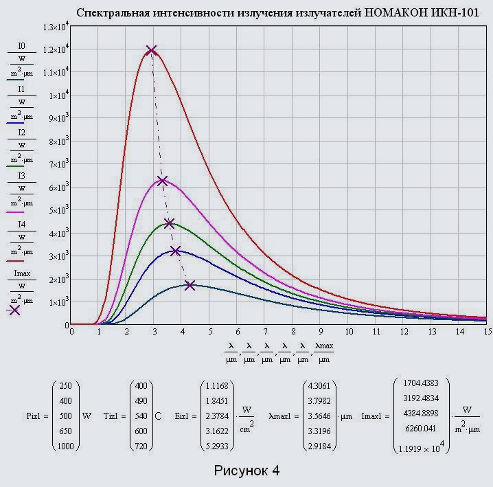
Figure 4 shows the characteristics of infrared radiation for ceramic emitters of the NOMAKON IKN-101 brand, obtained using expressions (3) - (5) with the degree of emissivity of the emitting surface ε1 = 0,96 and temperature of the emitting surface Tiz1 , ° C which corresponds to the electric power of the emitter Piz1 , W according to the technical characteristics presented in the table on the website page.
Calculated values of specific surface radiation energy Eiz1 , W / cm2 and the wavelength of the maximum spectral radiation intensity λmax1, μm are important characteristics for determining in the future the modes of operation of infrared electric heaters.
Analysis of the distribution of the radiation intensity by wavelengths (see Figure 4) in a wide range of values of the electric power of the emitters and the temperature of the emitting surface shows that the main radiation energy is generated in the wavelength range of 1.0-10 μm and includes the energy of the near (0 , 75-1.4 microns), medium (1.4-3 microns) and far (3-80 microns) radiation ranges. In this case, the wavelengths of 0-1.0 microns of the near and 10-80 microns of the far radiation ranges do not play a practical role in the process of infrared heating. Thus, the use of these emitters is justified for materials that absorb radiation well in the wavelength range of 1.0-10 microns with an absorption maximum at the peak of the maximum spectral radiation intensity in the wavelength range of 1.5-7.0 microns.
Characteristics of the emissivity of ceramic and quartz emitters
The development of methods for engineering calculation of infrared heating processes is of decisive importance in the design of equipment for technological processes, as well as for the selection of electric heaters and heating systems for industrial and domestic heating.
The methods presented below are based on a detailed analysis of the emissivity of the ceramic and quartz emitters developed by us, on the generalization of their measured and calculated basic characteristics depending on the size, shape and design features of the radiation surface.
The principle of operation of emitters is shown in Figure 5.
Ceramic emitters of the NOMACONTM IKN-100, IKN-200 and IKN-300 series are installed in a metal case with a reflector-reflector. Quartz emitters of the NOMAKON IKN-400 series have their own metal case. The description of the emitters, as well as their structural and connection dimensions, are presented on the corresponding pages of the site.
In the process of heating the radiation surface of ceramic emitters, as well as quartz tubes-emitters of quartz emitters, fluxes of radiant heat are formed, directed both outward from the heater into the environment and into the inside of the heater to the reflector-reflector and the housing.
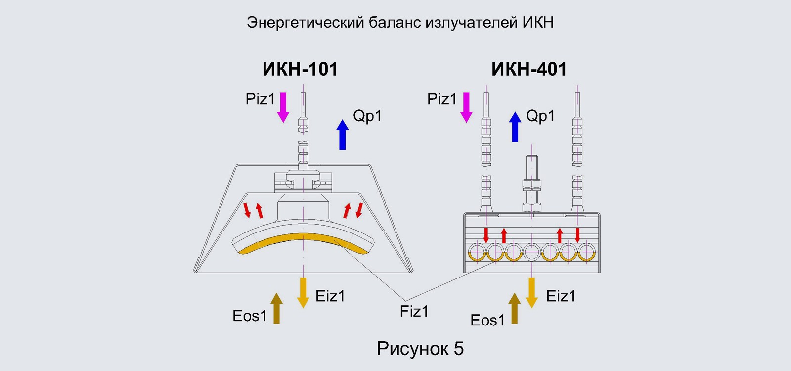
Partially reflected from the inner metal surfaces, infrared rays return to the emitting surface, further heating it and increasing the surface radiation energy outward Eiz1 ... Partial absorption of radiation causes heating of the reflector and housing. Additionally, the reflector and the heater body are heated from the inside by convective currents of hot air washing over the radiator. Thus, in a steady-state heating mode, the loss of heat energy Qp1 , W, i.e. that part of the energy that was not used to generate infrared radiation will be determined by heat losses to the environment from the heated heater body and heat losses from the heated air from the emitter. At the same time, the ambient infrared background radiation with a specific power will affect the emitting surface Eos1 , W / m2.
In the steady-state heating mode, the emitter consumes the nominal electrical power Piz1 , W and at the same time the energy conservation equation for the heater (energy balance) will take the form:

Where Fiz1 , m2 Is the estimated area of the radiation surface of the emitter.
Calculated radiation surface area
For the calculated area of the radiation surface of ceramic emitters of the NOMAKON TSC-100, TSC-200 and TSC-300 series, the geometric area of the outer surface of the ceramic emitters is taken from which radiant heat is mainly generated outward from the heater into the environment, and also on which the main reception of the background (reflected) radiation from the environment. It should be noted that the electric wire heating coil embedded in the ceramics is located the closest (at a distance of 1.5-2 mm) to the calculated radiating surface, marked in yellow in Figure 5.
The calculated area of the radiation surface of quartz emitters of the NOMACONTM IKN-400 series is taken to be the geometric area of the outer surface of quartz tubes-emitters from which radiant heat is mainly generated outward from the heater into the environment, and also on which the background (reflected) radiation from the environment is received. Wednesday. In this case, the surface of only those tubes in which the wire electric heating coil is installed is taken into account. The calculated radiation surface of the TSC-400 series emitters is marked in yellow in Figure 5.
The calculated values of the radiation surface for all series and standard sizes of the emitters are given in the tables "Technical characteristics" on the corresponding pages of the site.
Specific electrical power consumption
Since the radiation surface and the heating electric spiral are structurally related to each other, it is possible to assume that for TSC emitters of the same design (series), but different standard sizes (brands), the heating and infrared radiation generation modes will be identical, provided that the consumed electrical power per unit surface is equal radiation. Expression for calculating the specific electrical power consumption Poud1 , W / m2 will take the form:

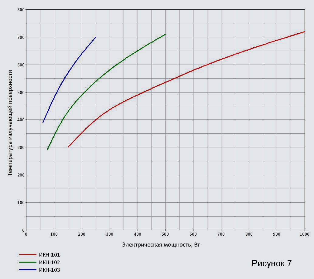
On the pages of emitters of the same series, there are universal graphs of their heating, depending on the consumed specific electrical power.
Radiating surface temperature
It is a definable parameter when calculating infrared heating modes. The "Specifications" tables on the emitter pages show the measured values of the emitting surface temperature Tiz1 , ° C depending on the rated electric power of the emitters Piz1 , W, or specific electrical power consumption Poud1 , W / m2.
Measurements of the temperature of the emitting surface of the TSC emitters were carried out by two methods.
- Contact method made it possible to continuously record heating and cooling curves using thermocouple microsensors of temperature rigidly fixed on the radiation surface (thermocouple TXA (K) with a measuring junction diameter of 0.5 mm) (see Figure 6).
- Contactless pyrometric method measuring the temperature of the radiating surface by its thermal radiation was used in a steady state to determine the emissivity (emissivity) of the radiating surface ε1
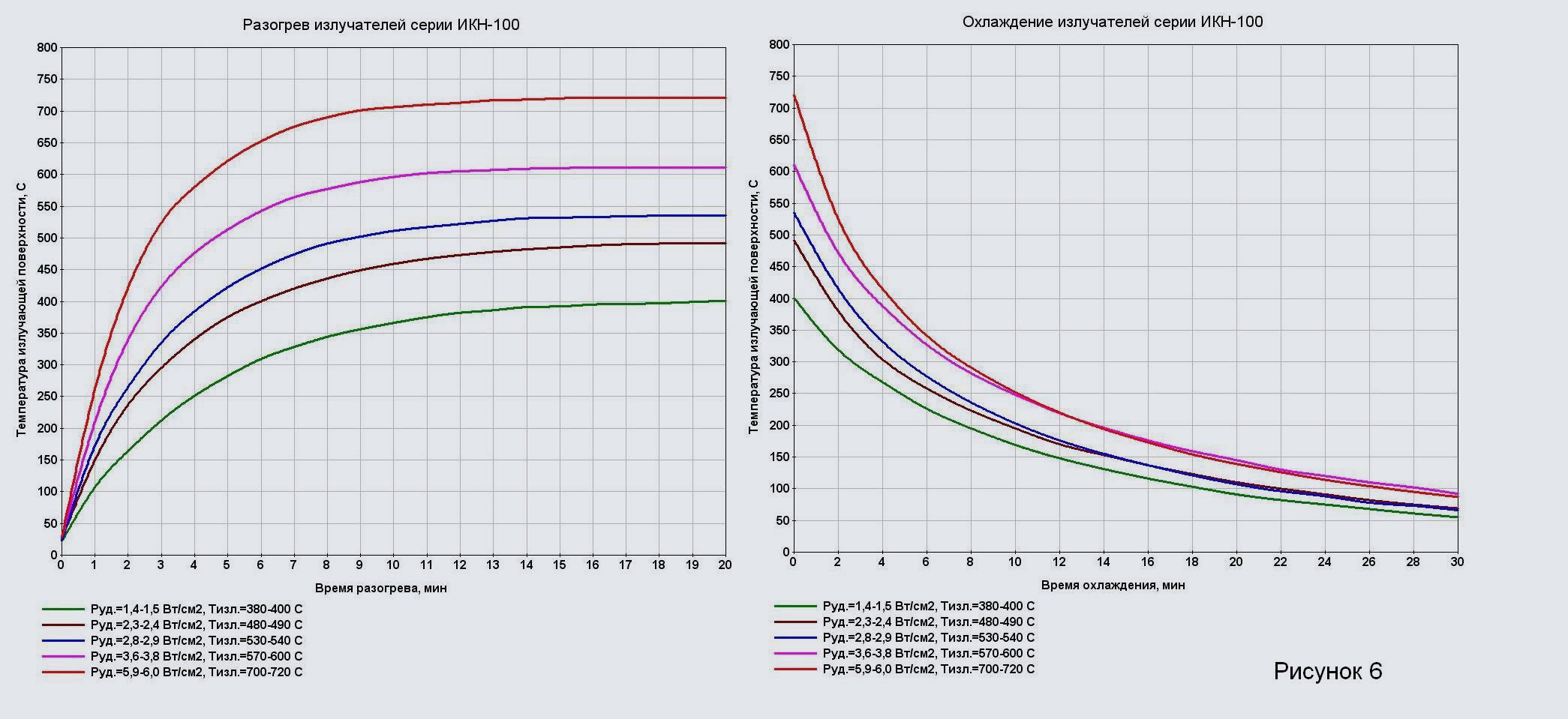
For the convenience of choosing the electric power of the emitters on the site pages, there are graphs of the dependence of the temperature of the emitting surface on the nominal electrical power consumption for various standard sizes of emitters within one series (see Figure 7).
Emissivity (or emissivity) ε1 shows the ratio of the energy of the thermal radiation of the "gray body" according to Stefan Boltzmann's Law to the radiation of the "absolutely black body (BBB)" at the same temperature. Blackbody emissivity εBlack body = 1 ... Based on the obtained measurement results in a wide range of radiation surface temperatures, with sufficient accuracy for engineering calculations, it is possible to take: for infrared ceramic emitters of the NOMAKON TSC-100, TSC-200 and TSC-300 series, the emissivity ε1 — 0,96 , for infrared quartz emitters of the NOMAKON TSC-400 series emissivity ε1 — 0,85 .
In infrared heating systems, the Kirchhoff's law for the heat flux absorbed by the material during heating is applied to calculate the temperature of the emitting surface (or the temperature of the emitters). Based on the energy balance of the emitters (see expression 6), it is possible to write

Where Em1 , W / m2 - specific radiation energy absorbed by a unit of material surface per unit of time, Eos1 , W / m2 - specific radiation energy of the material surface, having an average temperature during heating Tm1 , ° C. According to Kirchhoff's law
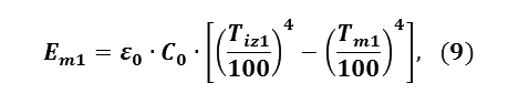
Where Tiz1 and Tm1 - absolute temperatures of the radiator and material in ° K, C0 = 5.671 W / (m2• K4) Is the constant of the Stefan-Boltzmann equation (see expression 5), ε0 Is the reduced emissivity of the "emitter - material" heating system.
Calculation expression ε0 has the form

Where ε1 and ε2 - respectively, the emissivity of the surface of the emitter and the surface of the material.
Having determined the value Em1 based on the heat balance of the heated material, it is possible to calculate the required temperature of the radiators from the expression (9):

Specific surface radiation energy
Determines the emitter radiation averaged over the calculated surface Fiz1 , cm2 generated specific radiant energy Eiz1 , W / cm2calculated from the temperature of the emitting surface Tiz1 by formula (5).
On the pages of the emitters in the tables "Technical characteristics" are given the values of the specific surface radiation energy depending on the temperature of the emitting surface Tiz1 , ° C.
Maximum radiation intensity wavelength and effective radiation wavelength range
Intensity maximum wavelength λmax1, μm determines the position of the maximum (peak) of the spectral radiation intensity Imax1 on the chart I = f (λ) (see Figure 4) and is calculated using Wien's equation (4). According to Wien's displacement law, with an increase in the temperature of the emitting surface, the values of the radiation intensity increase, and the radiation spectrum and, accordingly, the value λmax1 shift to the region of shorter radiation wavelengths.
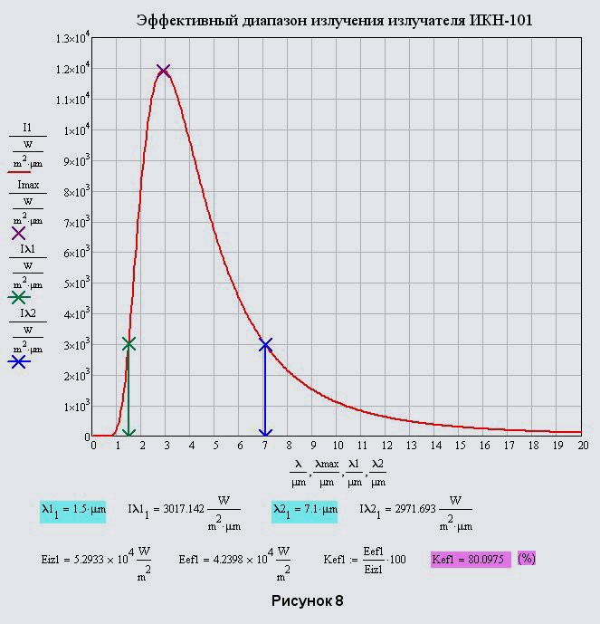
The calculation of the effective range of radiation wavelengths for a given temperature of the emitting surface is carried out under the condition that the specific radiation energy within the specified wavelength range should be 80% of the radiation energy calculated by the Stefan-Boltzmann equation (5) for the wavelength range from 0 to ∞ and at this value of the radiation intensity Iλ1 and Iλ2 at the boundaries of the wavelength range λ1 and λ2 must be equal. Thus, we exclude in engineering calculations a part of the near and far radiation ranges with a relatively low intensity, which insignificantly affects the infrared heating mode, and we believe that when designing infrared heating systems, it is the effective radiation wavelength range that, if possible, should overlap the region of the maximum absorption spectrum of the heated material.
The practice of designing and testing radiation heating devices shows that it is the effective radiation energy that is taken into account in the calculations. Eef1 , W / cm2 gives the results that are closest to experiments, especially for systems of high-speed infrared heating in the thermal shock mode.
Figure 8 shows the effective range of radiation wavelengths for TSC-101 ceramic emitters with electric power Piz1 = 1000 W at the temperature of the emitting surface Tiz1 = 720 ° Cobtained by numerically solving the system of equations (12) with respect to λ1 and λ2

Where Eef1, W / cm2 - specific effective radiation energy corresponding to the wavelength range from λ1 and λ2;
I (λ), (W / (m2• μm) - the current spectral intensity of radiation, calculated by the formula (3);
kef1 = 0,8 - the adopted efficiency factor (80 % of the total radiation energy).
Coefficient of emission of electrical energy into radiation energy (beam efficiency)
When heated with infrared ceramic and quartz TSC emitters, electrical energy is converted into thermal radiation energy, i.e. directly into the useful energy of thermal heating, and is also partially lost in the form of heat losses into the environment with the air heated from the heater body and from the radiators (see the energy balance of the TSC emitters in Figure 5). The greater the proportion of directed infrared energy in the total energy consumption of the heater, the more efficient the heating will be in terms of saving energy for infrared heating.
Thus, it is possible to compare the efficiency of various infrared heating devices by such an important indicator as the coefficient of emission of electrical energy into radiation energy or the radial efficiency (radial efficiency) ηem1, calculated as the ratio of the generated directed radiation energy to the total consumed electrical energy by the emitter Piz1 at steady state heating with the temperature of the radiating surface Tiz1... Based on the energy conservation equation for the emitter (6), the expression for calculating ηem1 will take the form:
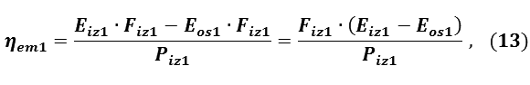
When heating rooms, the value of the radiation energy of the floor and walls of the room falling on the emitter in the amount of the radiant heating energy reflected from them is no more than Eos1 = 20-35 • W / m2, which is a completely insignificant amount compared to the surface radiation energy Eiz1 = 35000-52000 • W / m2... Thus, to calculate ηem1 in this case the value Eos1 can be neglected. If at the same time we express the consumed electricity Piz1 through specific electrical power consumption Poud1 (see formula 7), then expression (13) for ηem1 will take the form:

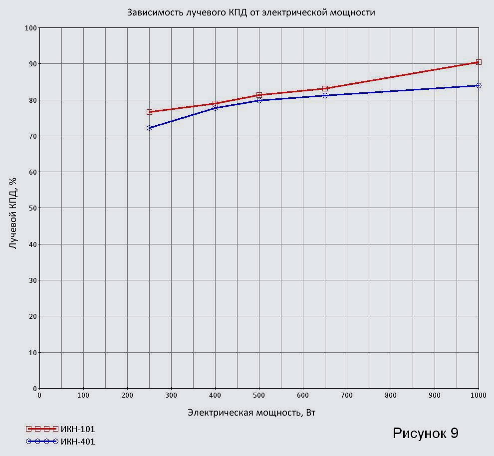
Specific electrical power consumption values (or electrical power per unit of radiating surface) Poud1 , W / cm2 and the values of the specific surface radiation energy Eiz1 , W / cm2, calculated for the measured corresponding temperatures of the emitting surface Tiz1are given in the "Specifications" tables on the emitter pages. Comparative values of the radial efficiency calculated by the formula (14). ηem1 for ceramic and quartz emitters of the NOMACONTM IKN-101 and IKN-401 brands are shown in Figure 9.
It should be noted that the structurally given characteristics Fiz1, Poud1 and Tiz1 ceramic emitter TSC-101 and quartz emitter TSC-401 are quite close. The discrepancies in the values of the radial efficiency are mainly associated with the lower value of the emissivity (emissivity) of a beam of quartz tubes (ε1= 0.85 for TSC-401) compared to the coating of ceramic elements (ε1= 0.96 for IKN-101).
Changing the characteristics of infrared radiation at different distances from the emitting surface
It should be noted that the characteristics of the distribution of the radiation heat from the radiators in space are significantly influenced by the design of the reflector-reflector, as well as the relative position of the radiators in the plane of the radiation zone of the heater.
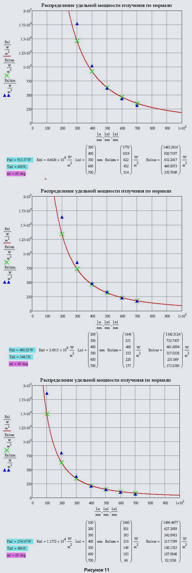
To calculate the specific power of infrared radiation at different distances from the emitting surface in the direction normal to this surface En1 = f (Ln1), W / m2 let's use the inverse square law for electromagnetic radiation.
With regard to the design of an infrared electric heater NOMAKON EIUS-211 with an infrared ceramic emitter IKN-101, it is possible to write:

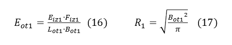
Where Eot1, W / m2 - specific radiation power, reduced to the area of the reflector-reflector of the heater;
Ln1, m - the current value of the distance from the radiation surface along the normal to this surface;
α1, deg. - the volumetric opening angle of the beam flux at the exit from the reflector-reflector;
R1, m - reduced radius of the beam flux at the exit from the reflector-reflector.
If we take the dimensions of the reflector-reflector in plan: length Lot1 = 250 mm, width Bot1 = 100 mm, then the expressions for calculating Eot1 and R1 take the form:
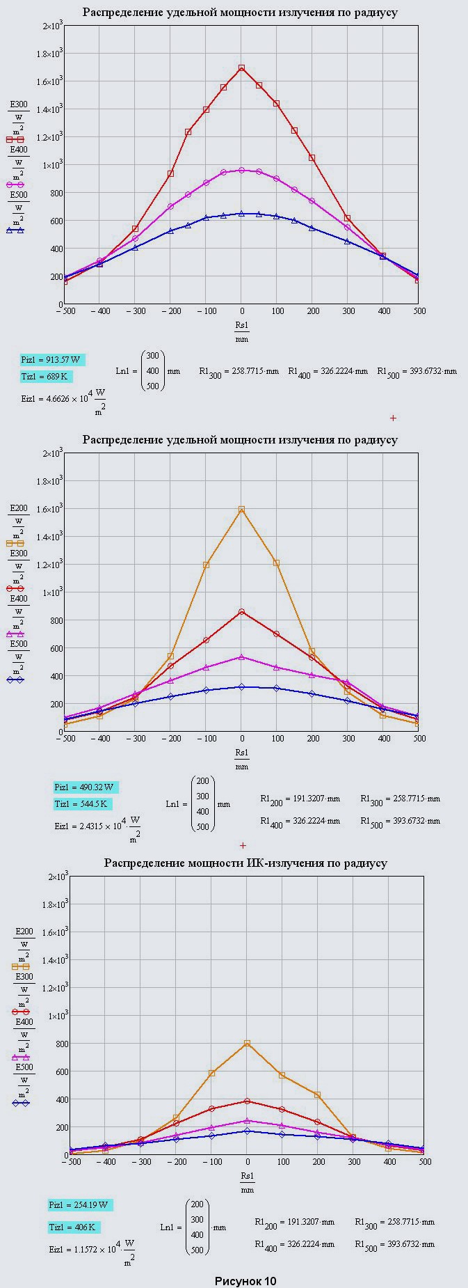
The volumetric opening angle of the beam flux at the exit from the reflector-reflector α1 was determined experimentally by measuring the distribution of the specific radiation power En1 normal at different distances Ln1 from the radiation surface. We also measured the distribution of the specific radiation power along the radius in the plane with the reduced radius of the ray flux Rs1, perpendicular to the normal and located at a distance Ln1 = 200, 300, 400 and 500 mm from the radiation surface. The measurements were carried out with an ARGUS-03 non-selective radiometer with an external thermoelement-receiver of radiation, which determines the average specific power in the spectral wavelength range from 0.5 to 20 μm. The tests were carried out for an EIUS-211 electric heater, installed horizontally with the radiation direction vertically downward, using TSC-101 emitters with an electric power of 1000, 500 and 250 W.
Processing diagrams of the distribution of the specific power of radiation at various distances from the radiation surface (see Figure 10) made it possible to calculate the average value of the opening angle of the beam flux for the reflector-reflector of the heater EIUS-211 α1= 68-72 °.
Figure 11 shows the graphs of the distribution of the specific radiation power along the normal to the emitting surface with the calculated values En1ras at measurement points Ln1 at a given value of the opening angle of the radiant flux α1= 68 °. Dots En1izm the data of measurements of the specific radiation power with a radiometer are noted.
The heater operation modes corresponded to the values Piz1, Tiz1 and Eiz1which are presented below the respective graphs.